Blog Number:-021
Hello everybody,
I hope you all will be fine.


Hello everybody,
I hope you all will be fine.
In the last Blog, We discussed about Static Machine(Transformer). In this session we will discuss about Rotating Machine(Motor). We will mainly focus on the DC motor. i.e. The motor which is powered by DC Signal.
DC Motor
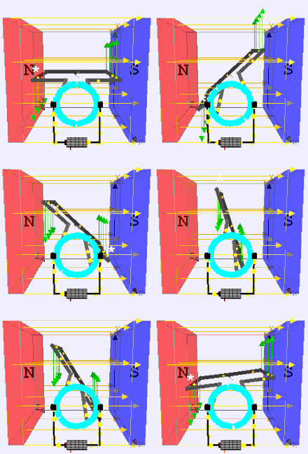
A DC motor is any of a class of rotary electrical machines that converts direct current electrical energy into mechanical energy. The most common types rely on the forces produced by magnetic fields. Nearly all types of DC motors have some internal mechanism, either electromechanical or electronic, to periodically change the direction of current flow in part of the motor.
A DC motor's speed can be controlled over a wide range, using either a variable supply voltage or by changing the strength of current in its field windings. Small DC motors are used in tools, toys, and appliances. Larger DC motors are used in propulsion of electric vehicles, elevator and hoists, or in drives for steel rolling mills.
A DC motor consists of two parts, a “Stator” which is the stationary part and a “Rotor” which is the rotating part. The result is that there are basically two types of DC Motor available.
- 1. Brushed Motor – This type of motor produces a magnetic field in the rotor by passing an electrical current through a commutator(A commutator is a moving part of a rotary electrical switch in certain types of electric motors and electrical generators that periodically reverses the current direction between the rotor and the external circuit) and carbon brush (The purpose of carbon brushes is to reduce wear on the commutator) assembly, hence the term “Brushed”. The stators (the stationary part) magnetic field is produced by using either a wound stator field winding or by permanent magnets. Generally brushed DC motors are cheap, small and easily controlled.
- 2. Brushless Motor – This type of motor produce a magnetic field in the rotor by using permanent magnets attached to it and commutation is achieved electronically. They are generally smaller but more expensive than conventional brushed type DC motors
Normal DC motors have almost linear characteristics with their speed of rotation being determined by the applied DC voltage and their output torque being determined by the current flowing through the motor windings. The speed of rotation of any DC motor can be varied from a few revolutions per minute (rpm) to many thousands of revolutions per minute making them suitable for electronic, automotive or robotic applications. By connecting them to gearboxes or gear-trains their output speed can be decreased while at the same time increasing the torque output of the motor at a high speed.
The “Brushed” DC Motor
A conventional brushed DC Motor consist basically of two parts, the stationary body of the motor called the Stator and the inner part which rotates producing the movement called the Rotor or “Armature” for DC machines.
The motors wound stator is an electromagnet circuit which consists of electrical coils connected together in a circular configuration to produce the required North-pole then a South-pole then a North-pole etc. The current which flows within these field coils is known as the motor field current.
These electromagnetic coils which form the stator field can be electrically connected in series, parallel or both together (compound) with the motors armature. A series wound DC motor has its stator field windings connected in series with the armature. Likewise, a shunt wound DC motor has its stator field windings connected in parallel with the armature as shown.
Conventional (Brushed) DC Motor

The Permanent magnet (PMDC) brushed DC motor is generally much smaller and cheaper than its equivalent wound stator type DC motor cousins as they have no field winding. In permanent magnet DC (PMDC) motors these field coils are replaced with strong rare earth (i.e. Samarium Cobolt, or Neodymium Iron Boron) type magnets which have very high magnetic energy fields.
The use of permanent magnets gives the DC motor a much better linear speed/torque characteristic than the equivalent wound motors because of the permanent and sometimes very strong magnetic field, making them more suitable for use in models, robotics and servos.
Although DC brushed motors are very efficient and cheap, problems associated with the brushed DC motor is that sparking occurs under heavy load conditions between the two surfaces of the commutator and carbon brushes resulting in self generating heat, short life span and electrical noise due to sparking, which can damage any semiconductor switching device such as a MOSFET or transistor. To overcome these disadvantages, Brushless DC Motors were developed.
The “Brushless” DC Motor
The brushless DC motor (BDCM) is very similar to a permanent magnet DC motor, but does not have any brushes to replace or wear out due to commutator sparking. Therefore, little heat is generated in the rotor increasing the motors life. The design of the brushless motor eliminates the need for brushes by using a more complex drive circuit.
The control of the brushless DC motors is very different from the normal brushed DC motor, in that it this type of motor incorporates some means to detect the rotors angular position (or magnetic poles) required to produce the feedback signals required to control the semiconductor switching devices. The most common position/pole sensor is the “Hall Effect Sensor”, but some motors also use optical sensors. Using Hall effect sensors, the polarity of the electromagnets is switched by the motor control drive circuitry.
Advantages of the Brushless DC Motor compared to its “brushed” cousin is higher efficiencies, high reliability, low electrical noise, good speed control and more importantly, no brushes or commutator to wear out producing a much higher speed. However their disadvantage is that they are more expensive and more complicated to control.
So, That's all for the day.
If you have any doubt related to topic, please comment.
Thank you.


No comments:
Post a Comment