Blog Number:-013
Hello Everybody,
Well, I hope you all will be fine.
So, that's all for this session. If you have any doubt regarding the topic. please comment.
Thank you,
Have a good day Ahead.
Hello Everybody,
Well, I hope you all will be fine.
In the last session, we had discussed about Rectifier(which convert AC signal in DC signal), And AC signal is having an standard value(i.e. 230V) but we need an DC signal of 12V, In that case first we decrease the level of AC signal from 230V to 12V and then using Rectifier, we convert AC signal into DC signal.
Now, take an another case, we need an DC signal of 12V as well as 5V from one source, In that case we will first decrease the level of AC signal from 230V to 12V and then Rectify it. From it we will get 12V DC signal. To get another 5V signal, We will use a Voltage Regulator of 5V through 12V DC output.
Voltage Regulator:-
 |
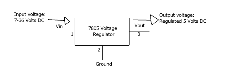
| 7805 voltage regulator |
A voltage regulator generates a fixed output voltage of a preset magnitude that remains constant regardless of changes to its input voltage or load conditions.
Or, A voltage regulator is a voltage stabilizer that is designed to automatically stabilize a constant voltage level. A voltage regulator circuit is also used to change or stabilize the voltage level according to the necessity of the circuit. Thus, a voltage regulator is used for two reasons:-
- To regulate or vary the output voltage of the circuit.
- To keep the output voltage constant at the desired value in-spite of variations in the supply voltage or in the load current.
Voltage regulators find their applications in computers, alternators, power generator plants where the circuit is used to control the output of the plant. Voltage regulators may be classified as electro-mechanical or electronic. It can also be classified as AC regulators or DC regulators.
DC regulator-
A voltage regulator is a device with a simple feed- forward design and it uses negative feedback control loops. There are mainly two types of voltage regulators: Linear voltage regulators and switching voltage regulators.
Linear Voltage Regulator
Linear regulator acts like a voltage divider. In Ohmic region, it uses FET. The resistance of the voltage regulator varies with load resulting in constant output voltage.
Voltage regulator uses a variable element(Control Element) placed in series with the load. By changing the resistance of that series element, the voltage dropped across it can be changed. And, the voltage across the load remains constant.
 |
| Voltage regulator block Diagram |
we are giving input signal through Vin. The Control element is a type of potentiometer whose resistance depends on the input signal level and is controlled in order to make the output signal always constant. Reference voltage is a Preset voltage at which we have to make our output voltage constant. Sampling circuit is the circuit which take a sample signal from output. Comparator circuit is a circuit which compare the sampling circuit value and the reference voltage. The output from comparator circuit goes to Control element in order to adjust the resistance of potentiometer. And in this way the value of output voltage always remain constant
Advantages of linear voltage regulator
- Gives a low output ripple voltage
- Fast response time to load or line changes
Disadvantages of linear voltage regulator
- Efficiency is very low
- Requires large space – heatsink is needed
- Voltage above the input cannot be increased
Physically Available Voltage Regulator
78xx (sometimes L78xx, LM78xx, MC78xx...) is a family of self-contained fixed linear voltage regulator integrated circuits for positive voltage. There are common configurations for 78xx ICs, including 7805 (5 V), 7806 (6 V), 7808 (8 V), 7809 (9 V), 7810 (10 V), 7812 (12 V), 7815 (15 V), 7818 (18 V), and 7824 (24 V) versions.
79xx voltage regulators are very commonly used in electronic circuits. The main purpose of this IC is to supply required regulated negative voltage to the circuits. IC 79xx can supply a constant negative voltage output, in spite of any voltage fluctuations in its input voltage. It can be mainly found in the circuits in which integrated circuits that require +Vcc and – Vcc are used.
Pin Diagram Of 78XX
Thank you,
Have a good day Ahead.
No comments:
Post a Comment