Blog Number:-006
Hello Everybody,
In the last blog, we have discussed about Basic Gates(i.e AND, OR, NOT Gate). Now in this blog, we will proceed further and will discuss about some more Logic Gates which are also called Universal Gates and can be designed using Basic Gates and some other Gates.
In Universal Gates categories, we have NAND Gate and NOR Gate. EX-OR/XOR Gate, EX-NOR/XNOR Gate are some other Gates. So, lets discuss one by one.
Logic NAND Gate:-

The Logic NAND Gate is a combination of the digital logic AND gate with that of an inverter or NOT gate connected together in series.
In other word, We can also define NAND gate as- A NOT-AND operation is known as NAND operation. It has n input (n >= 2) and one output.

The NAND gate operates as an AND gate followed by a NOT gate. It acts in the manner of the logical operation "and" followed by negation. The output is "false" if both inputs are "true." Otherwise, the output is "true."
The NAND gate gives us the Boolean expression of: A.B = Q.
2-input Logic NAND Gate Truth Table
| Symbol | Truth Table | ||

2-input NAND Gate
| B | A | Q |
| 0 | 0 | 1 | |
| 0 | 1 | 1 | |
| 1 | 0 | 1 | |
| 1 | 1 | 0 | |
| Boolean Expression Q = A.B | Read as A AND B gives NOT Q | ||

The Logic NOR Gate or Inclusive-NOR gate is a combination of the digital logic OR gate with that of an inverter or NOT gate connected together in series.
In other word, We can also define NOR gate as- A NOT-OR operation is known as NOR operation. It has n input (n >= 2) and one output.

The NOR gate is a combination OR gate followed by an inverter. Its output is "true" if both inputs are "false". Otherwise, the output is "false".
the NOR gate gives us the Boolean expression of: A+B = Q.
2-input NOR Gate Truth Table
| Symbol | Truth Table | ||

2-input NOR Gate
| B | A | Q |
| 0 | 0 | 1 | |
| 0 | 1 | 0 | |
| 1 | 0 | 0 | |
| 1 | 1 | 0 | |
| Boolean Expression Q = A+B | Read as A OR B gives NOT Q | ||

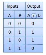
an logic output “1” is obtained when ONLY A = “1” or when ONLY B = “1” but NOT both together at the same time, giving the binary inputs of “01” or “10”, then the output will be “1”. This type of gate is known as an Exclusive-OR Gate or more commonly an Ex-Or Gate.
In other words, the output of an Exclusive-OR gate ONLY goes “HIGH” when its two input terminals are at “DIFFERENT” logic levels with respect to each other.
An odd number of logic “1’s” on its inputs gives a logic “1” at the output. These two inputs can be at logic level “1” or at logic level “0” giving us the Boolean expression of: Q = (A B) = A.B + A.B.

2-input EX-OR Gate Truth Table
Logic EX-NOR/XNOR Gate

The Exclusive-NOR Gate function or Ex-NOR for short, is a digital logic gate that is the reverse or complementary form of the Exclusive-OR function.
An output “1” is only obtained if BOTH of its inputs are at the same logic level, either binary “1” or “0”. For example, “00” or “11”. This input combination would then give us the Boolean expression of: Q = (A B) = A.B + A.B.
The output of a digital logic Exclusive-NOR gate ONLY goes “HIGH” when its two input terminals, A and B are at the “SAME” logic level which can be either at a logic level “1” or at a logic level “0”. In other words, an even number of logic “1’s” on its inputs gives a logic “1” at the output, otherwise is at logic level “0”.


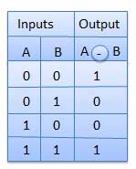
The logic symbol for an Exclusive-NOR gate is simply an Exclusive-OR gate with a circle or “inversion bubble”, ( ο ) at its output to represent the NOT function. Then the Logic Exclusive-NOR Gate is the reverse or “Complementary” form of the Exclusive-OR gate.

2-input EX-NOR Gate Truth Table
So, This is what the Digital Logic Gates are, If you have any problem regarding the topic then feel free to comment.
and those who didn't read my Blog number-4, which was based on Basic Logic Gate, please follow the link given below.
Thank you.
No comments:
Post a Comment