Blog number:-031
Hello everybody,
I hope you all will be fine.
Today, in this session we will start discussion on Wireless Communication. Communication means share of information between transmitter and receiver. and Wireless communication means passing of information without use of any physical channel. We will discuss various method of Wireless Communication. Today we will focus on Radio Frequency(RF) based Wireless Communication.
RF based Wireless Communication is done with the help of RF module which comes with various operating frequency.
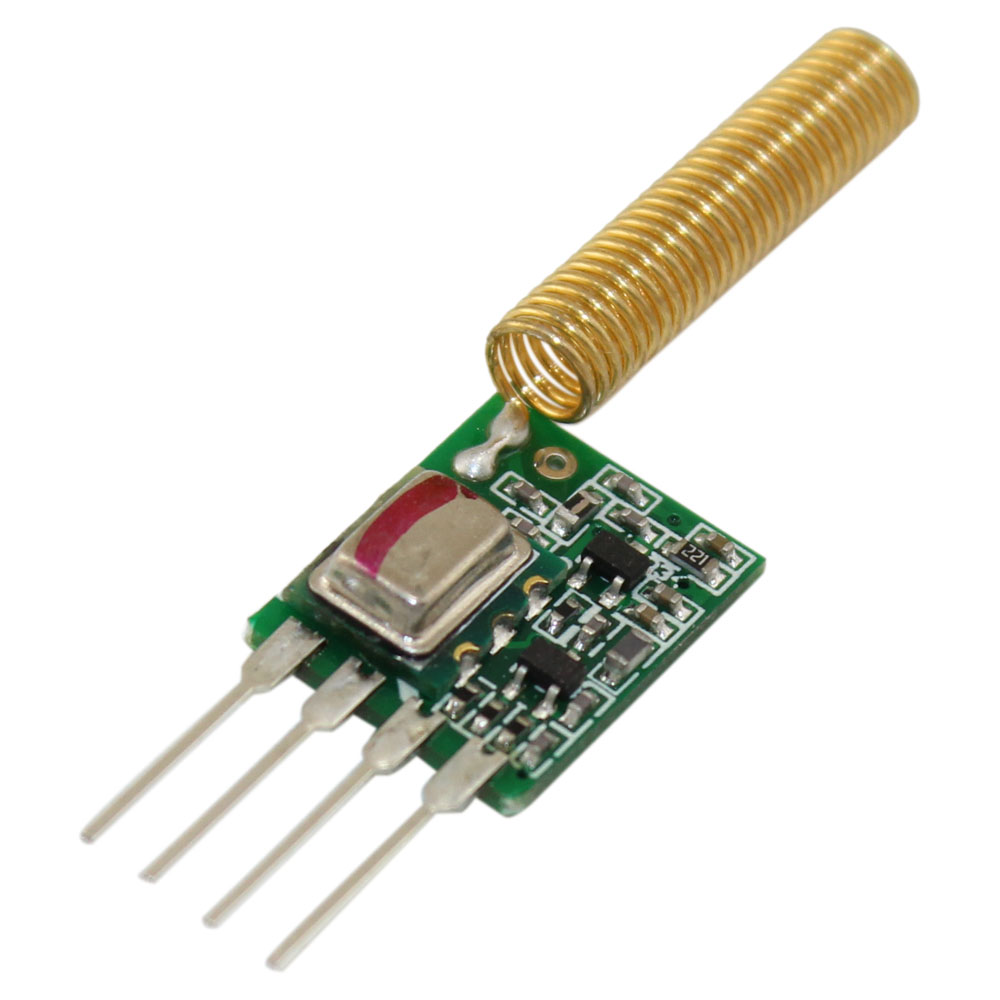
RF Module:-

wireless communication may be accomplished through optical communication or through radio frequency (RF) communication. An RF module (radio frequency module) is a (usually) small electronic device used to transmit and/or receive radio signals between two devices. For many applications the medium of choice is RF since it does not require line of sight.
Several carrier frequencies are commonly used in commercially available RF modules, including those in the industrial, scientific and medical (ISM) radio bands such as 433.92 MHz, 915 MHz, and 2400 MHz. Short Range Devices may also use frequencies available for unlicensed such as 315 MHz and 868 MHz.
Types of RF module
Transmitter modules
An RF transmitter module is a small PCB sub-assembly capable of transmitting a radio wave and modulating that wave to carry data. Transmitter modules are usually implemented alongside a micro controller which will provide data to the module which can be transmitted.
Receiver modules
An RF receiver module receives the modulated RF signal, and demodulates it.

The RF module is often used alongwith a pair of encoder/decoder. The encoder is used for encoding parallel data for transmission feed while reception is decoded by a decoder. HT12E-HT12D, HT640-HT648, etc. are some commonly used encoder/decoder pair ICs.
Pin Diagram-

Pin Description:
RF Transmitter
Pin No
|
Function
|
Name
|
1
|
Ground (0V)
|
Ground
|
2
|
Serial data input pin
|
Data
|
3
|
Supply voltage; 5V
|
Vcc
|
4
|
Antenna output pin
|
ANT
|
RF Receiver
Pin No
|
Function
|
Name
|
1
|
Ground (0V)
|
Ground
|
2
|
Serial data output pin
|
Data
|
3
|
Linear output pin; not connected
|
NC
|
4
|
Supply voltage; 5V
|
Vcc
|
5
|
Supply voltage; 5V
|
Vcc
|
6
|
Ground (0V)
|
Ground
|
7
|
Ground (0V)
|
Ground
|
8
|
Antenna input pin
|
ANT
|
Transmitter circuit diagram
HT12E Encoder IC will convert the 4 bit parallel data given to pins D0 – D3 to serial data and will be available at DOUT. This output serial data is given to ASK RF Transmitter. Address inputs A0 – A7 can be used to provide data security and can be connected to GND (Logic ZERO) or left open (Logic ONE). Status of these Address pins should match with status of address pins in the receiver for the transmission of the data. Data will be transmitted only when the Transmit Enable pin (TE) is LOW. 1.1MΩ resistor will provide the necessary external resistance for the operation of the internal oscillator of HT12E.
Receiver Circuit Diagram

ASK RF Receiver receives the data transmitted using ASK RF Transmitter. HT12D decoder will convert the received serial data to 4 bit parallel data D0 – D3. The status of these address pins A0-A7 should match with status of address pin in the HT12E at the transmitter for the transmission of data. The LED connected to the above circuit glows when valid data transmission occurs from transmitter to receiver. 51KΩ resistor will provide the necessary resistance required for the internal oscillator of the HT12D.
So, that's all for this session. If you have any doubt related to topic, please comment.
Thank you.
No comments:
Post a Comment