Blog Number:-002
Well, I wish you all will be fine and healthy.
In my last blog, I have discussed about Resistor. Now, In this session we will discuss about Capacitors.
Capacitors:-
Introduction-
Introduction-
 |
| Various Types Of Capacitor |
What makes capacitors special is their ability to store energy; they’re like a fully charged electric battery. Caps, as we usually refer to them, have all sorts of critical applications in circuits. Common applications include local energy storage, voltage spike suppression, and complex signal filtering.
Symbols and Units-
Circuit Symbols
There are two common ways to draw a capacitor in a schematic. They always have two terminals, which go on to connect to the rest of the circuit. The capacitors symbol consists of two parallel lines, which are either flat or curved; both lines should be parallel to each other, close, but not touching (this is actually representative of how the capacitor is made. Hard to describe, easier to just show:
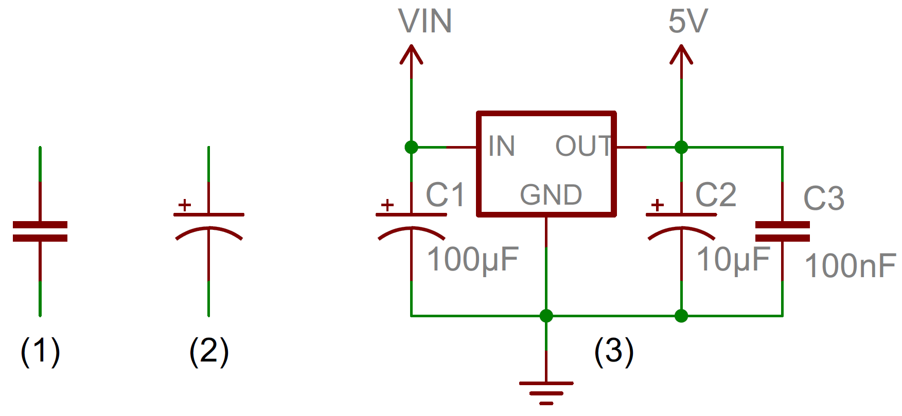
(1) and (2) are standard capacitor circuit symbols. (3) is an example of capacitors symbols in action in a voltage regulator circuit.
The symbol with the curved line (#2 in the photo above) indicates that the capacitor is polarized, meaning it’s probably an electrolytic capacitor. More on that in the types of capacitors section of this tutorial.
Each capacitor should be accompanied by a name – C1, C2, etc.. – and a value. The value should indicate the capacitance of the capacitor; how many farads it has. Speaking of farads…
Capacitance Units-
Not all capacitors are created equal. Each capacitor is built to have a specific amount of capacitance. The capacitance of a capacitor tells you how much charge it can store, more capacitance means more capacity to store charge. The standard unit of capacitance is called the farad, which is abbreviated F.
It turns out that a farad is a lot of capacitance, even 0.001F (1 milifarad – 1mF) is a big capacitor. Usually you’ll see capacitors rated in the pico- (10-12) to microfarad (10-6) range.
| Prefix Name | Abbreviation | Weight | Equivalent Farads |
|---|---|---|---|
| Picofarad | pF | 10-12 | 0.000000000001 F |
| Nanofarad | nF | 10-9 | 0.000000001 F |
| Microfarad | µF | 10-6 | 0.000001 F |
| Milifarad | mF | 10-3 | 0.001 F |
| Kilofarad | kF | 103 | 1000 F |
When you get into the farad to kilofarad range of capacitance, you start talking about special caps called super or ultra-capacitors.
Capacitor Theory-
How a Capacitor Is Made
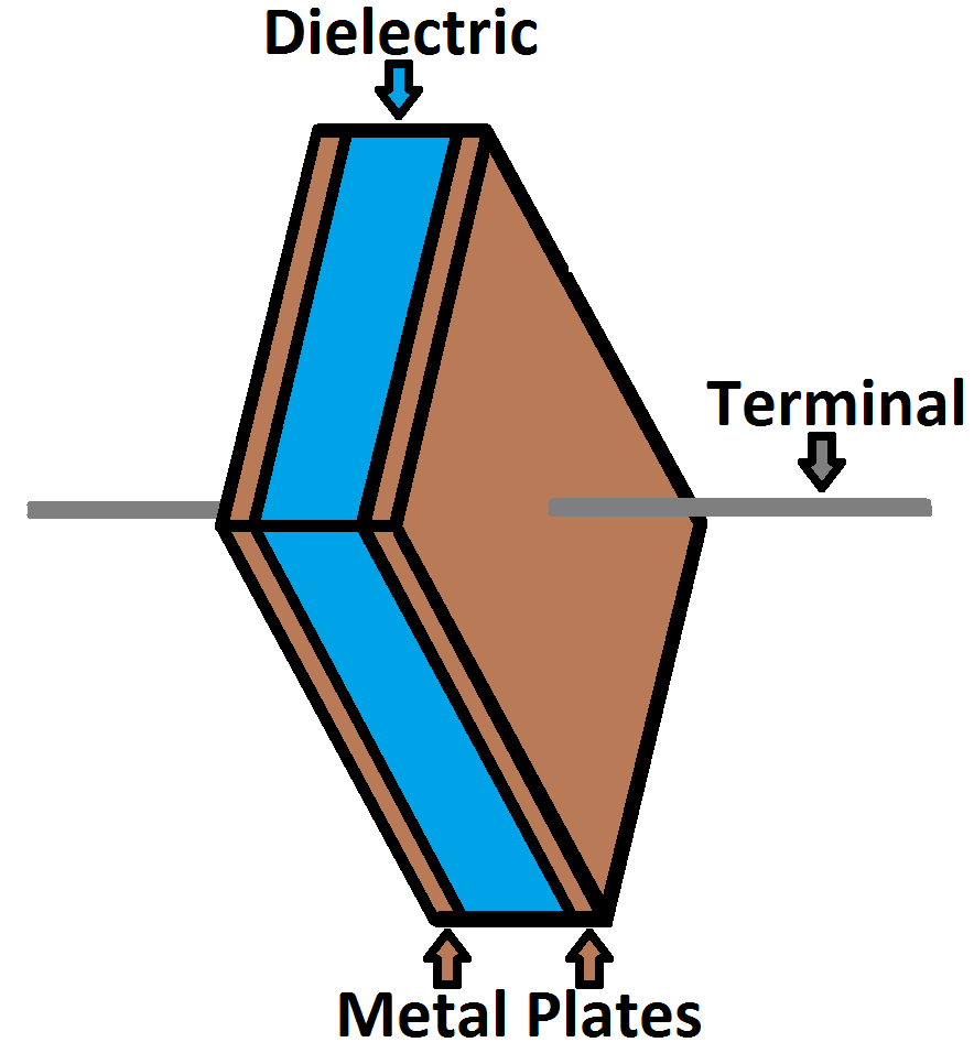
The schematic symbol for a capacitor actually closely resembles how it’s made. A capacitor is created out of two metal plates and an insulating material called a dielectric. The metal plates are placed very close to each other, in parallel, but the dielectric sits between them to make sure they don’t touch.

The dielectric can be made out of all sorts of insulating materials: paper, glass, rubber, ceramic, plastic, or anything that will impede the flow of current.
The plates are made of a conductive material: aluminum, tantalum, silver, or other metals. They’re each connected to a terminal wire, which is what eventually connects to the rest of the circuit.
The capacitance of a capacitor – how many farads it has – depends on how it’s constructed. More capacitance requires a larger capacitor. Plates with more overlapping surface area provide more capacitance, while more distance between the plates means less capacitance. The material of the dielectric even has an effect on how many farads a cap has. The total capacitance of a capacitor can be calculated with the equation:
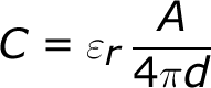 Where εr is the dielectric’s relative permittivity (a constant value determined by the dielectric material), A is the amount of area the plates overlap each other, and d is the distance between the plates.
How a Capacitor Works
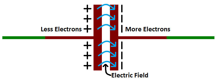
Electric current is the flow of electric charge, which is what electrical components harness to light up, or spin, or do whatever they do. When current flows into a capacitor, the charges get “stuck” on the plates because they can’t get pass the insulating dielectric. Electrons – negatively charged particles – are sucked into one of the plates, and it becomes overall negatively charged. The large mass of negative charges on one plate pushes away like charges on the other plate, making it positively charged.
 The positive and negative charges on each of these plates attract each other, because that’s what opposite charges do. But, with the dielectric sitting between them, as much as they want to come together, the charges will forever be stuck on the plate (until they have somewhere else to go). The stationary charges on these plates create an electric field, which influence electric potential energy and voltage. When charges group together on a capacitor like this, the cap is storing electric energy just as a battery might store chemical energy.
Charging and Discharging
When positive and negative charges accumulate near the capacitor plates, the capacitor becomes charged. A capacitor can retain its electric field – hold its charge – because the positive and negative charges on each of the plates attract each other but never reach each other.
At some point the capacitor plates will be so full of charges that they just can’t accept any more. There are enough negative charges on one plate that they can repel any others that try to join. This is where the capacitance (farads) of a capacitor comes into play, which tells you the maximum amount of charge the cap can store.
If a path in the circuit is created, which allows the charges to find another path to each other, they’ll leave the capacitor, and it will discharge.
For example, in the circuit below, a battery can be used to induce an electric potential across the capacitor. This will cause equal but opposite charges to build up on each of the plates, until they’re so full they repel any more current from flowing. An LED placed in series with the cap could provide a path for the current, and the energy stored in the capacitor could be used to briefly illuminate the LED.
Capacitors in Series/Parallel:-
Much like resistors, multiple capacitors can be combined in series or parallel to create a combined equivalent capacitance. Capacitors, however, add together in a way that’s completely the opposite of resistors.
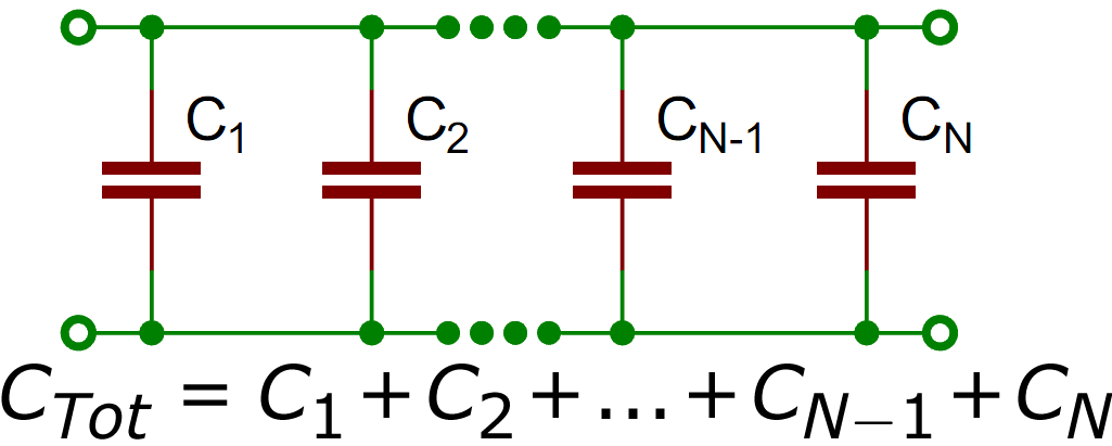
Capacitors in Parallel
When capacitors are placed in parallel with one another the total capacitance is simply the sum of all capacitances. This is analogous to the way resistors add when in series.
 So, for example, if you had three capacitors of values 10µF, 1µF, and 0.1µF in parallel, the total capacitance would be 11.1µF (10+1+0.1).
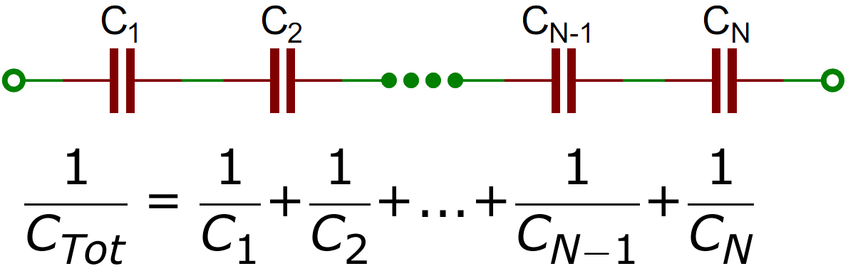
Capacitors in Series-
Much like resistors are a pain to add in parallel, capacitors get funky when placed in series. The total capacitance of N capacitors in series is the inverse of the sum of all inverse capacitances.
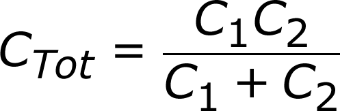
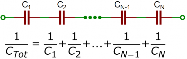 If you only have two capacitors in series, you can use the “product-over-sum” method to calculate the total capacitance:
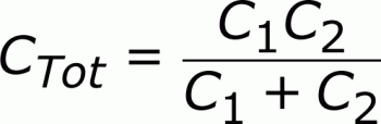 Taking that equation even further, if you have two equal-valued capacitors in series, the total capacitance is half of their value. For example two 10F supercapacitors in series will produce a total capacitance of 5F (it’ll also have the benefit of doubling the voltage rating of the total capacitor, from 2.5V to 5V).
Thats all for the Session, Well you have any Doubt regarding the topic, Feel free to ask.
Thank you,
Er. Rahul Kumar
No comments:
Post a Comment